Overview
During use of the Sparx sharpener, the grinding ring used to sharpen ice skates creates steel sparks/shavings/dust from each blade; the front door, top covers, and internal filtration system help to contain these shards inside the machine during operation
The existing filtration system works by using a centrifugal fan during operation to contain the steel sparks and draw larger shavings into a HEPA-type filter by creating negative pressure inside the main chamber of the device, before exhausting air from the blower outside the machine
The goal of the project was to develop of an entirely new filtration system assembly that fit a new, smaller cavity on the inside of the Sparx sharpener using a more powerful axial blower; this system contains the following components:
Filter Housing: Main injection-molded component of filtration system used as duct for airflow and as a base to attach other components
24V Axial Fan: stimulate airflow and create negative pressure in the machine
Fan Grille: cover the fan from the external face of the machine and protect users
HEPA-type Filter: filter steel sparks/shavings/dust created during skate sharpening
2x Filter Clamps: used to secure and lock down filter to filter housing
Filter Limit Switch: used to detect presence of filter in machine and ensure machine isn’t used without filter
Many of the FDM prototype iterations for the filter housing design
Testing of intermediate prototype for fan grille (yellow) and filter housing (grey) on Sparx sharpener
Final (top) vs. First (bottom) FDM prototypes of the filter housing
CAD assembly of fan grille with blower, showing angled blower inside the filter system
View of final injection molded filter housing, filter clamps, and filter limit switch from inside the machine
Same view as above with HEPA-type filter installed
Final injection molded fan grille
Process
Tested baseline airflow statistics in current filtration system by running sharpener through entire filter life and measuring changes in filter weight (added weight due to sparks/shavings/dust) and negative pressure between filter and blower
Designed and 3D printed preliminary prototype of filter housing with minimum duct sizing for testing on modified Sparx sharpener to accommodate new design and blower to compare to current filtration system
Completed several design and 3D printed prototype iterations to improve airflow efficiency and optimize size capacity
Used master modelling technique on SolidWorks for design of the filter housing and fan grille within Sparx sharpener assembly to ensure compatibility and easily update as other changes were made
Designed and determined specifications for filter with new size and features
Designed filter clamps for intuitive and simple use, visual aesthetics, and strong “feel” to snap in place when used properly
Modified design of filter housing, fan grille, and filter clamps to allow for plastic injection molding manufacturing, including added drafts, changing tolerances, gate location, and acceptable ejector pin locations
Created manufacturing 2D drawings for all parts with critical dimensions, appropriate section views, material, and texturing details
complications
Airflow duct design through compact space was very difficult, and original estimates assuming tight turns in airflow had to be redesigned and optimized several times
Original dimensions specified for filter system were too small to allow for proper airflow, requiring other design changes in the Sparx machine to allow for more space
Injection molding process for filter housing system requires several lifters and sliders; communication with manufacturers was essential throughout the design process to ensure successful manufacturing process
Results
Completed advanced SolidWorks design of three injection molded pieces with production-level 2D drawings
Optimized airflow through new filter housing to maximize differential negative pressure while minimizing size
Effectively decreased size of filtration system within Sparx sharpener and simultaneously increasing negative pressure and flow within the machine
Skills Developed
Master modelling technique and advanced injection molding design on SolidWorks, including the use of surface modeling and several other advanced features
Airflow fluid mechanics understanding and experience through iterative design testing and empirical data
Product design process leadership from concept to production
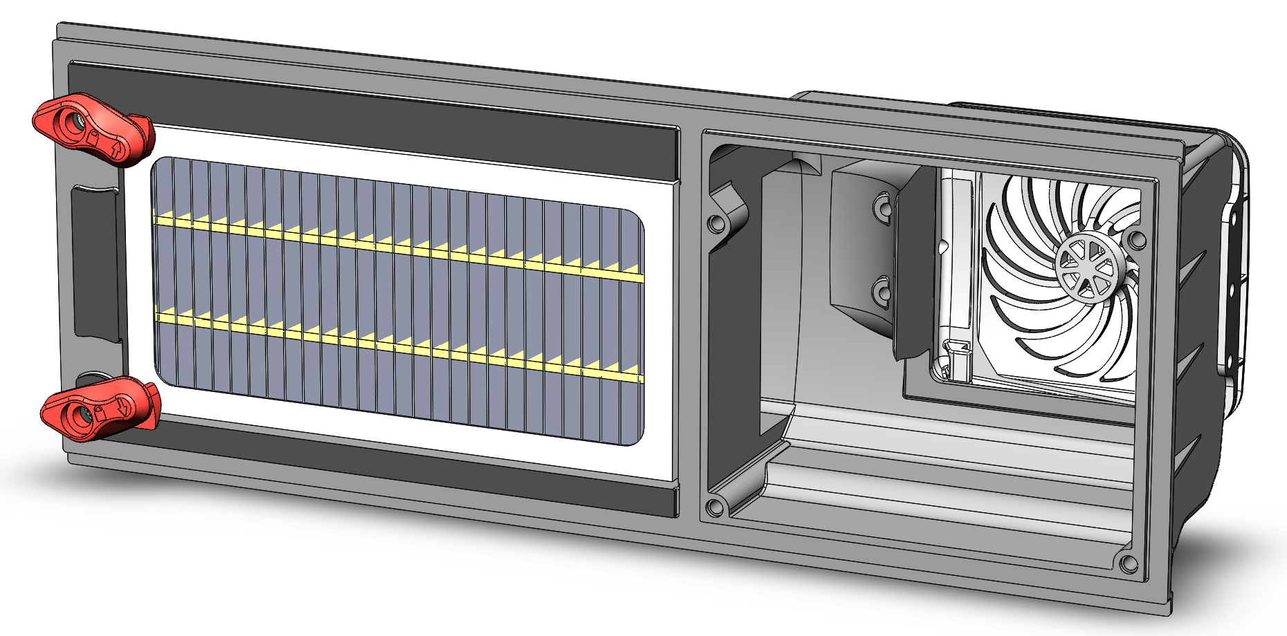
Final CAD assembly of filter system, showing filter housing (largest component, grey), filter clamps (red), filter (white and yellow), and fan grille (white)


