Overview of My Projects


Below you will find detailed descriptions of a sampling of the exciting projects that I have undertaken during my experience at Northeastern, including on my three co-op experiences, and as personal hobbies. If you have any questions about these projects, feel free to reach out to me! I am always happy to talk about my work and how my past projects have contributed to my professional development.

 
Initial concept sketch (above) and final frame, drive, and steering assembly (below)

Initial concept sketch (above) and final frame, drive, and steering assembly (below)

Executive Summary Draft Picture.jpg

 Overview

  • Capstone Senior Design project for Northeastern University, completed July-December 2019 with teammates Filip Adamowicz, Jake Peabody, Nicolas Fong, and Darryl Robinson

  • Skating on ice degrades the surface  quality over time. To maintain ice quality, rinks require a method of resurfacing. Efficient solutions exist for full-scale ice rinks (i.e. the Zamboni) but do not exist for small-scale or “backyard” ice rinks. The most common backyard solution is to water the rink with a hose, which is time-consuming and labor-intensive, as well as an inefficient use of large volumes of water. Creative DIY solutions exist, but there is no solution capable of efficiently creating quality ice comparable to that of a professional Zamboni. A preliminary patent search which was completed for my Capstone project yielded no inhibitors to this idea.

  • The problem statement was to design and develop a device to resurface small-scale backyard ice rinks

  • The project was divided into five main subsections: frame, drivetrain, steering/suspension, water dispersion, and controls system. I led the development of the frame and controls system, and my team collaborated throughout all phases of the project.

Process

  • Designed and fabricated frame out of 1” 8020 aluminum extrusion, and completed SolidWorks FEA to ensure strength

  • Led development and programming of microcontrollers for radio frequency control of onboard electronics via a handheld remote controller through use of Arduinos and RF transceivers

  • Spearheaded all electrical circuit building and wire management of the project, including development of onboard and handheld circuit systems

  • Machined several steel components for steering and drivetrain using lathe and bandsaw

Complications

  • Frame development was instrumental to all other subsystems and had to be carefully designed to accommodate the needs of other team members’ subsystems early in the design stage

  • Lack of expert programming or microcontroller knowledge required several weeks of work to learn and apply the necessary skills for controlling high current systems and converting them to RF controls

  • Low temperature and wet environment of outdoor ice resurfacing required careful attention to battery and material selection, as well as proper insulation of the electrical control system

SolidWorks frame design, labeling key joints and brackets used

SolidWorks frame design, labeling key joints and brackets used

SolidWorks finite element analysis showing axial stress areas

SolidWorks finite element analysis showing axial stress areas

Electrical circuit diagram for onboard controller

Electrical circuit diagram for onboard controller

Results

  • A fully operational prototype ice resurfacer vehicle, operated via handheld remote controller, was developed

    • Frame size constrained by onboard 20 gallon water tank, final vehicle dimensions of approximately 4’ x 2’ x 2’

    • Handheld remote controller to toggle drive motor (on/off), water pump (on/off), and steering (joystick) via RF Arduino control

    • Rear-wheel drive vehicle powered by 12V DC motor with studded tires for additional traction on ice

    • Rigid suspensions steering system using rack and pinion controlled by a stepper motor

    • Water dispersion system from storage tank through pressure control value and pump, water dispersed via four fine mist flat spray nozzles

  • The device drastically cuts down on time, effort, and water quantity required to create resurfaced ice, while simultaneously increasing the surface quality and user experience when compared to traditional hose resurfacing

  • The initial prototype proved concept feasibility, and a second generation prototype and business model are currently in production through funding and coaching from Northeastern’s IDEA Venture Accelerator

IMG_4729 (1).gif
IMG_4533.jpg
IMG_4730 (1).gif

Skills Developed

  • Advanced Solidworks Weldments features used for design and simulation of the vehicle’s frame

  • Microcontroller (Arduino) programming skills for integration of DC motors, stepper motors, relays, and RF transceivers

  • Electrical circuit development for high current systems, including usage of current splitters, relays, motor controllers, fuses, and voltage regulators

  • Various methods for soldering of electrical connections

  • Further experience in metal machining including manual lathe, mill, bandsaw, and aluminum chop saw

Overview

  • During use of the Sparx sharpener, the grinding ring used to sharpen ice skates creates steel sparks/shavings/dust from each blade; the front door, top covers, and internal filtration system help to contain these shards inside the machine during operation

  • The existing filtration system works by using a centrifugal fan during operation to contain the steel sparks and draw larger shavings into a HEPA-type filter by creating negative pressure inside the main chamber of the device, before exhausting air from the blower outside the machine

  • The goal of the project was to develop of an entirely new filtration system assembly that fit a new, smaller cavity on the inside of the Sparx sharpener using a more powerful axial blower; this system contains the following components:

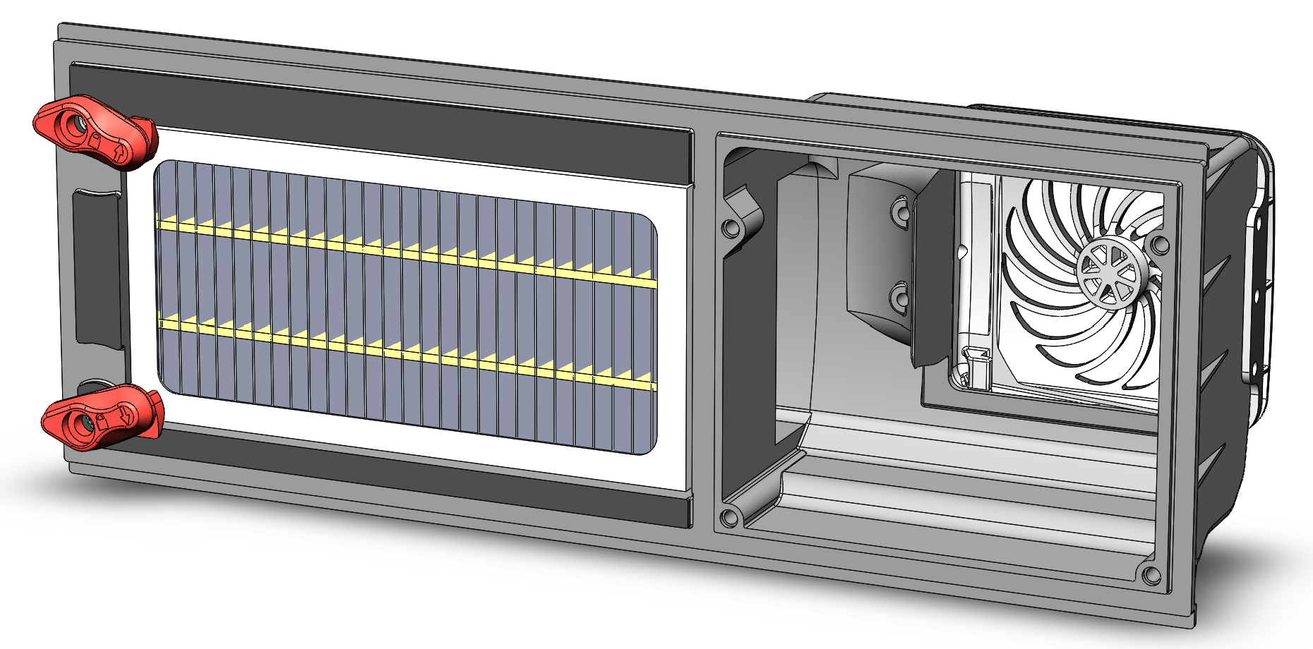
    • Filter Housing: Main injection-molded component of filtration system used as duct for airflow and as a base to attach other components

    • 24V Axial Fan: stimulate airflow and create negative pressure in the machine

    • Fan Grille: cover the fan from the external face of the machine and protect users

    • HEPA-type Filter: filter steel sparks/shavings/dust created during skate sharpening

    • 2x Filter Clamps: used to secure and lock down filter to filter housing

    • Filter Limit Switch: used to detect presence of filter in machine and ensure machine isn’t used without filter

Many of the FDM prototype iterations for the filter housing design

Many of the FDM prototype iterations for the filter housing design

Testing of intermediate prototype for fan grille (yellow) and filter housing (grey) on Sparx sharpener

Testing of intermediate prototype for fan grille (yellow) and filter housing (grey) on Sparx sharpener

Final (top) vs. First (bottom) FDM prototypes of the filter housing

Final (top) vs. First (bottom) FDM prototypes of the filter housing

CAD assembly of fan grille with blower, showing angled blower inside the filter system

CAD assembly of fan grille with blower, showing angled blower inside the filter system

View of final injection molded filter housing, filter clamps, and filter limit switch from inside the machine

View of final injection molded filter housing, filter clamps, and filter limit switch from inside the machine

Same view as above with HEPA-type filter installed

Same view as above with HEPA-type filter installed

Final injection molded fan grille

Final injection molded fan grille

Process

  • Tested baseline airflow statistics in current filtration system by running sharpener through entire filter life and measuring changes in filter weight (added weight due to sparks/shavings/dust) and negative pressure between filter and blower

  • Designed and 3D printed preliminary prototype of filter housing with minimum duct sizing for testing on modified Sparx sharpener to accommodate new design and blower to compare to current filtration system

  • Completed several design and 3D printed prototype iterations to improve airflow efficiency and optimize size capacity

    • Used master modelling technique on SolidWorks for design of the filter housing and fan grille within Sparx sharpener assembly to ensure compatibility and easily update as other changes were made

  • Designed and determined specifications for filter with new size and features

  • Designed filter clamps for intuitive and simple use, visual aesthetics, and strong “feel” to snap in place when used properly

  • Modified design of filter housing, fan grille, and filter clamps to allow for plastic injection molding manufacturing, including added drafts, changing tolerances, gate location, and acceptable ejector pin locations

  • Created manufacturing 2D drawings for all parts with critical dimensions, appropriate section views, material, and texturing details

complications

  • Airflow duct design through compact space was very difficult, and original estimates assuming tight turns in airflow had to be redesigned and optimized several times

  • Original dimensions specified for filter system were too small to allow for proper airflow, requiring other design changes in the Sparx machine to allow for more space

  • Injection molding process for filter housing system requires several lifters and sliders; communication with manufacturers was essential throughout the design process to ensure successful manufacturing process

Results

  • Completed advanced SolidWorks design of three injection molded pieces with production-level 2D drawings

  • Optimized airflow through new filter housing to maximize differential negative pressure while minimizing size

  • Effectively decreased size of filtration system within Sparx sharpener and simultaneously increasing negative pressure and flow within the machine

Skills Developed

  • Master modelling technique and advanced injection molding design on SolidWorks, including the use of surface modeling and several other advanced features

  • Airflow fluid mechanics understanding and experience through iterative design testing and empirical data

  • Product design process leadership from concept to production

Final CAD assembly of filter system, showing filter housing (largest component, grey), filter clamps (red), filter (white and yellow), and fan grille (white)

Final CAD assembly of filter system, showing filter housing (largest component, grey), filter clamps (red), filter (white and yellow), and fan grille (white)

 Overview

  • The Sparx ice skate sharpener is an electro-mechanical device, relying on several electronics to control and operate the mechanical components

  • Once the mechanical design stage of development and a Top Level Assembly with all parts included were completed, drawings had to be created for electrical components for suppliers that provided wire specifications and lengths

  • Sparx main PCB control board utilized JST connectors for quick connect/disconnect; thus, electrical drawings had to include these with proper orientation

Example of limit switch wire harness with component and 3D wire routing, for determining wire and heat shrink tubing length as well as for visual indication during assembly

Example of limit switch wire harness with component and 3D wire routing, for determining wire and heat shrink tubing length as well as for visual indication during assembly

Process

  • List of 10+ electro-mechanical components within Sparx sharpener that needed specified wire lengths and production drawings was generated

  • Used top level assembly of Sparx sharpener to interpret placement of all electronics and spec wire lengths for production

  • Used SolidWorks configurations to create three versions of all electronic devices- component only, component with 3D wire routing, and component with straight wires for 2D production drawings

Example of AC power input configuration, with specific wire orientation for stacking during assembly and JST connector

Example of AC power input configuration, with specific wire orientation for stacking during assembly and JST connector

complications

  • Had to learn design of simple electrical circuits and custom Sparx PCB to understand wiring

  • Wire harnesses were not created with master modelling like the rest of the assembly, and thus changes had to be manually updated with each design change

Results

  • Created 2D production drawings for all electro-mechanical components within Sparx sharpener

  • Specified wire orientation for JST connectors’ attachment to PCB and routing through machine

Skills Developed

  • Knowledge of electro-mechanical product specifications and PCB connections

  • Use of advanced SolidWorks Configurations feature to create multiple variations of each part

2D drawing example of LED Splice

2D drawing example of LED Splice

2D drawing example of AC power input configuration

2D drawing example of AC power input configuration

2D drawing example of filtration system blower

2D drawing example of filtration system blower

Overview

  • Purge Cassette: device used to support the Abiomed Impella heart pumps by pumping dextrose into the heart pump to equalize pressure and prevent backflow of blood through the pump’s catheter

  • Project was developed to redesign the pumping mechanism in order to improve product performance and reduce manufacturing cycle time save time and money during production

  • After preliminary testing, areas for improvement on the pump cylinder arose that needed redesign

  • My role: aid with design improvements to the pump cylinder (see figure) and spearhead all modeling using SolidWorks

Process

  • Redesigned outflow (pressure) port to match ISO 80369-7:2016 for small-bore connectors for liquids and gases in healthcare applications

  • Created new inflow (suction) port with modified tubing stops to prevent occlusion and add ease of assembly

  • Drew and released r02 SolidWorks part for pump cylinder

  • Drew and released r02 SolidWorks drawings for pump cylinder, rack, and piston head

Gen 1 Pump Assembly currently in production

Gen 1 Pump Assembly currently in production

Gen 2 Pump Assembly (r02) designed by me

Gen 2 Pump Assembly (r02) designed by me

r02 Pump Cylinder, indicating the locations of the pressure port and suction port that were redesigned

r02 Pump Cylinder, indicating the locations of the pressure port and suction port that were redesigned

Complications

  • Had to interpret ISO 80369-7 drawings in order to fit design of cylinder pressure port

  • Had to “fill in” ports and rebuild them entirely in order to make changes to part because SolidWorks part was imported as STEP file from Pro E

  • Part drawing format at Abiomed changed during the project and I had to learn the new format while also updating the existing drawing

Isometric view of pressure port

Isometric view of pressure port

 
Top view of redesigned suction port, with three-quarter ring tubing stops

Top view of redesigned suction port, with three-quarter ring tubing stops

Cross sectional view showing factors considered when converting pressure port to ISO 80369-7:2016 standards

Cross sectional view showing factors considered when converting pressure port to ISO 80369-7:2016 standards

 
Cross sectional view showing modified tubing stop height

Cross sectional view showing modified tubing stop height

Results

  • Released r02 part design for pump cylinder with port improvements to resolve complications during preliminary testing

  • Released r02 drawings for pump cylinder, rack (syringe plunger body), and piston (syringe plunger head)

  • Created and released article specifications for all three components

  • Tested ports on molded parts to confirm increased strength and ease of purge cassette assembly

  • Purge cassette redesign projected to save the organization $3 million annually

Skills Developed

  • Product design techniques in SolidWorks, especially through modifying imported models

  • Official drawing and document release process with doc control and supplier communications

  • Adapting designs and drawings to account for injection molding process

r01 Drawing, with my redline markups

r01 Drawing, with my redline markups

r02 Drawing with revisions made to part, notes, injection molding indications, and format

r02 Drawing with revisions made to part, notes, injection molding indications, and format

Overview

  • Citizen Lathe area of manufacturing floor adding a new lathe (5 —> 6 machines)

  • Plenty of room for improvement in product and operator workflow maps

  • Workstations are cluttered and unorganized

Process

  • Recorded Activity of the Operator (AOO) and Activity of the Product (AOP) for major product families

  • Indicated areas for improvement in floor layout, workstation redesign, and time management with product planning by analyzing AOO and AOP videos

  • Created workflow maps from AOP videos, revealing wasted product movement and Work In Progress (WIP) stations

  • Redesigned floor layout to make room for new machine and improve product workflows

  • Organized workstations using 6S techniques to remove unnecessary tools and materials

  • Designed and ordered custom shadow boards for tools and desk supplies

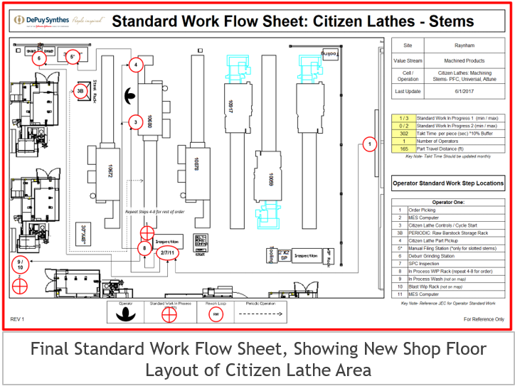
Final Standard Work Flow Sheet created for the new Citizen Lathe area, with new floor layout, ,custom template and all operator location steps

Final Standard Work Flow Sheet created for the new Citizen Lathe area, with new floor layout, ,custom template and all operator location steps

One of the machine operators working with the new floor layout

One of the machine operators working with the new floor layout

Backend process workstation, highlighting 6S integration and organization

Backend process workstation, highlighting 6S integration and organization

Lathe Shadow-Boards.png
Pictured above are the two shadow boards designed- the top image is for lathe tooling, and the bottom image is for go/no-go pin gauges

Pictured above are the two shadow boards designed- the top image is for lathe tooling, and the bottom image is for go/no-go pin gauges

cOMPLICATIONS

  • Filming and analyzing AOO & AOP took a tremendous amount of time (videos were 3-6 hrs long), delaying the project

  • Had to order new workstation desks that were smaller and able to fit in the new layout design

  • Shadow board production by third-party vendor were made incorrectly and had to be redesigned and reordered

Results

  • New floor layout improved product flow and fit new lathe machine to increase production capacity

  • Shadow boards and organized workstations increased efficiency and achieve more continuous flow

  • Designed new Standard Work Flow Sheet and Six Sigma posters, to be implemented in all shop floor areas in future projects

Skills Developed

  • Lean techniques for improving efficiency of production in manufacturing processes

  • Six Sigma process of improving appearance and performance of workstations

  • Design of manufacturing floor to maximize workflows

Me doing general upkeep on one of my mountain bikes

Me doing general upkeep on one of my mountain bikes

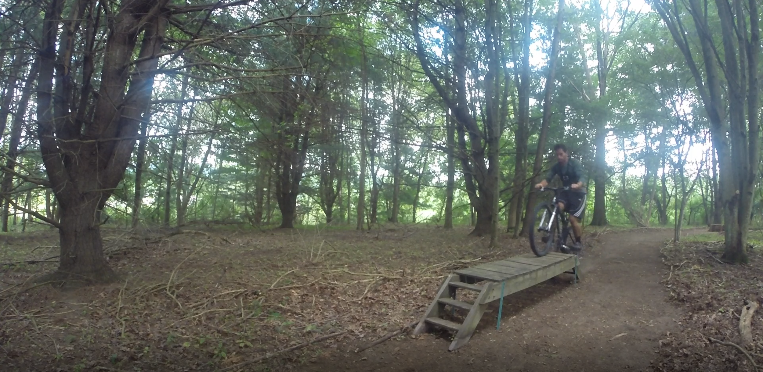
Screenshot of video from my perspective on a bike of the trail

Screenshot of video from my perspective on a bike of the trail

Summer 2018 addition of bike teeter-totter

Summer 2018 addition of bike teeter-totter

 Overview

  • Multi-acre area of undeveloped woods behind my home

  • Shared passion with my dad for mountain biking

  • Wanted an area close to home to ride and have fun

  • Recently got into downhill mountain biking and wanted an area to improve on jumps and features

Process

  • Walked through woods and developed rough trail layout

  • Cleared brush, grass, trees, and bushes where necessary

  • Raked trail and laid stick borders along length to clearly mark the trail

  • Used tractor to build jumps and dig out larger areas

  • Converted old walking bridge to bike feature and moved it to the woods

  • Built miscellaneous features including log jumps, banked turns, and a teeter-totter

  • Filmed all progress with GoPro cameras

  • Process is ongoing to-date; new additions are added whenever I am able to return home

Results

  • Completed 500+ yard mountain bike trail full of jumps and unique features

  • Edited and posted GoPro video of initial trail work during Summer 2017

  • Mastered mountain bike riding through trail

Skills Developed

  • Bike trail development and maintenance techniques

  • Adapted woodworking skills to bike feature creation

  • Further honed skills with GoPro filming and post-video editing on iMovie

GoPro edit of the transformation of my backyard woods into a mountain biking trail, complete with unique and complex features (Summer 2017) . I used my Specialized FSR XC throughout this video.

Overview

  • Cornhole is a common lawn game played by tossing several bean bags across a distance to try to either get the bag to stay on the board (1 pt) or go into the small hole (3pt), played with two teams of two members to a score of 21

  • I wanted to have my own set of high-quality cornhole boards, complete with custom paint jobs for Northeastern University

Process

  • Crafted two 4’ x 2’ cornhole boards through use of basic woodshop machines, hand tools, and dremel for fine detail

  • Designed a custom paint job for Northeastern University, including traditional cornhole triangle shapes and hand-painted Northeastern logos to maximize aesthetic value

  • Coated boards with polyurethane layers for waterproofing and surface finish

  • Hand sewed bean bags for cornhole game and filled them with artificial weighted corn pellets

Results

  • Completed a fully customized cornhole set with Northeastern colors and logos

  • Hosted a cornhole tournament with friends and family (and unfortunately lost in the first round)

Skills Developed

  • Further extension of woodworking experience and fine dremel work

  • Artistic creativity through custom paint job and cornhole board design

IMG-3343.jpg
 
Construction of frames out of plywood and 2x4s

Construction of frames out of plywood and 2x4s

Painting of traditional cornhole triangles

Painting of traditional cornhole triangles

Addition of Northeastern logos with custom stencil

Addition of Northeastern logos with custom stencil

Raw oak board

Raw oak board

Rough surface and bark finish, with several nature cracks

Rough surface and bark finish, with several nature cracks

 Overview

  • Moved to a new studio apartment, wanted a thin but functional console table to sit behind the couch to be used as a kitchen table as well as a working surface (WFH due to COVID-19)

  • Couldn’t find a table that we liked, so I decided to build it myself from a piece of wood and metal table legs

Process

  • Found a 52”x10”x1.75” piece of rough cut oak wood with bark edge to be used as the table surface; purchased four 28” metal table legs from a custom vendor with welded mounting brackets for attaching it to the underside of the table

  • Glued and sealed several cracks and holes along the length of the wood board using wood glue and furniture clamps

  • Cut board to final length and width using table saw to square off all sides

  • Sanded most wood surfaces of the wood with belt sander, mouse sander, and sandpaper (up to 400 grit), lightly sanded bark edge by hand to keep rustic finish; this step was repeated again after wiping the surface with a damp cloth to ensure final smooth finish

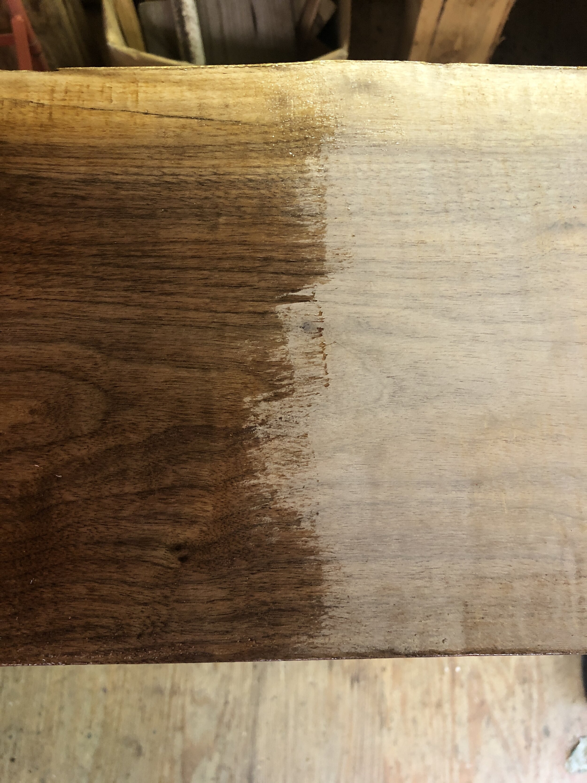
  • Painted 3-5 coats of indoor semi-gloss polypropylene on all surfaces of the board to fill natural knots, ensure waterproof seal, and prevent warping

  • Spray painted metal table legs black

  • Attached table legs to the underside of the table with wood screws and shimmed as necessary to ensure stable surface

Sanding the board with belt and mouse sanders

Sanding the board with belt and mouse sanders

Color pop from semi-gloss poly finish

Color pop from semi-gloss poly finish

Oak board drying between poly coats

Oak board drying between poly coats

Results

  • Beautiful custom oak console table with final dimensions of 50”x9.75”x29.5”

Skills Developed

  • Further experience with hand and power woodworking tools (table saw, belt sander, mouse sander, drill)

  • Furniture woodworking skills including managing weight-bearing joints, leveling, and surface finishing

Finished table with legs attached

Finished table with legs attached